 Bullard Industrial Technologies, Inc.
Est. 1981
Induction Generation
One of the most overlooked sources of energy savings in an industrial, institutional or manufacturing setting and one that has been around for several decades is the induction electrical generator.
There are two types of alternating current generators. The synchronous generator and the induction generator. The synchronous generator operates in parallel with the local utility or with other synchronous generators running on the same system. It requires an exciter to provide DC power to excite the rotor field and a synchronizing control system to enable it to run at the synchronous speed of the utility (grid) or other generators with which it is operating in parallel. The speed of the generator controls the power generated (kilowatts). It also requires a voltage regulator to control the reactive power (kilovars) generated.
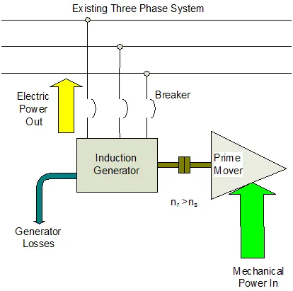
The induction generator like any other generator converts mechanical energy into electrical energy. An induction generator, also known as an asynchronous generator, is a type of alternating current generator that utilizes the principle of induction motors to produce electrical power. Induction generators operate by mechanically turning their rotors slightly faster than synchronous speed which produces an active current in the stator coils and the machine then operates as a generator sending power back to the grid. The induction generator consists of a rotating element (rotor) and a stationary element (stator). The rotor consists of a copper or aluminum “squirrel cage” within the rotor laminations. The stator consists of insulated copper windings within the stator laminations. Reactive power (excitation) is supplied by the grid. Simply put, an induction generator is an induction motor specially designed and wound to produce power instead of consume it.
Induction Generator Starting Sequence:
1. Breaker open.
2. Increase prime mover mechanical input until nr > ns
3. Close breaker
4. Adjust the mechanical power to match the electric load. Pmech = Pe + Ploss
How induction generators work:
-
An AC supply is connected to the stator terminals of an induction machine. A rotating magnetic field produced in the stator pulls the rotor to run behind it (the machine is acting as a motor).
-
If the rotor is accelerated to the synchronous speed by means of a prime mover, the slip will be zero and hence the net torque will be zero. The rotor current will become zero when the rotor is running at synchronous speed.
-
If the rotor is made to rotate at a speed more than the synchronous speed, the slip becomes negative. A rotor current is generated in the opposite direction, due to the rotor conductors cutting stator magnetic field.
-
This generated rotor current produces a rotating magnetic field in the rotor which pushes (forces in the opposite way) onto the stator field. This causes a stator voltage which pushes current flowing out of the stator winding against the applied voltage. Thus, the machine is now working as an induction generator (asynchronous generator).
Two factors affect the advantages of the induction generator over the synchronous generator: The design of the generator and the prime mover used to drive the generator.
Design cost savings design advantages include:
- No field excitation is required. Excitation is provided by the grid.
- No voltage regulator is required as voltage and frequency are provided by the connected utility.
- Much simpler construction when compared with a synchronous generator. No brushes, diodes or collector rings are required.
- No synchronizer control is required as the generator is not running in parallel with the grid. It is already connected to the grid via its circuit breaker.
- Maintenance costs are lower as there are fewer components and controls.
Prime movers include reciprocating diesel, natural gas or propane engines, combustion turbines and steam turbines. The disadvantage of reciprocating engines and combustion turbines include:
- Fuel cost to operate. Typically, there is a purchase cost associated with the fuel required for reciprocating engines or combustion turbines.
- Even “renewable” fuels such as landfill gas and digester gas have significant conditioning and process costs related to delivering them to the end-user machine.
Steam turbines represent the most cost effective and viable prime mover for an induction generator providing there is a demand for the exhaust steam from the turbine:
- Any steam plant that generates at least 100 psi steam and has lower pressure steam systems currently provided by pressure reducing valves (PRVs) can utilize induction generation.
- Low pressure steam required for building heat, process work, feedwater deaeration, food preparation, absorption chillers, etc. that is supplied from a pressure reducing valve results in 100% of the steam lost to the low pressure system. Utilizing a backpressure steam turbine to drive a rotating machine and then using the exhaust steam for the low pressure system results in re-use of the majority of the heat in the steam for the low pressure needs and eliminates the cost of running an induction electric motor.
When there is sufficient low pressure steam load in a facility, steam turbine drives are also an attractive alternative to induction electric motors to drive rotating equipment such as pumps, blowers and fans.
Steam turbines require only 2,545 BTUs per horsepower per hour to drive the turbine. The balance of the heat is used to satisfy the low pressure steam load for the facility. Using the constants 778 foot pounds per BTU and 33,000 foot pounds per minute per horsepower this factor is calculated as follows:
33,000 x 60 minutes = 1,980,000 ft. lbs per hour/778 = 2,544.9871 BTUs per hour.
As an example, consider a 480 volt motor control center with and average load of 300 kw. At .746 kw per horsepower this load would require a 400 hp generator to supply the load.
This 400 horsepower steam turbine with a water rate of 50 lbs/hp/hr at 150 psi (1,196 btu/lb enthalpy) will have a steam consumption of 400 hp x 50 lb/hp/hr = 20,000 lbs/hr.
400 x 2,545 = 1,018,000 btu/hr to operate the turbine = 1,018,00/1,196 = 851 lbs/hr of steam to drive the turbine. 20,000 – 851 = 19,149 lbs/hr available as exhaust steam to use for low pressure steam applications.
Using worst/best case scenarios, at $14.00 per thousand pounds of steam and $0.05 /kwh for an electric cost (including KW, demand and power factor charges), the following table illustrates the cost savings associated with operating the steam turbine driven induction generator in this example:
Cost to Operate the Steam Turbine
851 x 24 = 20,424 lbs/day consumed by the turbine. 20,424/1,000 = 20.42 x $14.00/thousand lbs = $285 per day to drive the steam turbine.
Electric Savings from the Induction Generator
300kw x $0.05/kwh = $15 x 24 = $360/day savings by generating 300kw. $360 – $285 = $75/day savings.
$75 x 365 = $27,375 annual savings from operating the induction generator.
Steam costs lower than the example and/or electric costs higher than the example result in a greater savings and faster return-on-investment (ROI) when utilizing steam turbine driven induction generators. Larger horsepower applications also result greater savings at a comparable ratio to the 400 hp example.
The key to the cost savings feasibility is to have sufficient low pressure steam demand to accept 100% of the exhaust steam available from the steam turbine drive. Low pressure steam sources to consider are: deaerating feedwater heater, fuel oil heating systems, building heating systems, large capacity domestic water heaters supplied by steam, absorption chillers, instrument sterilization, humidification, etc.
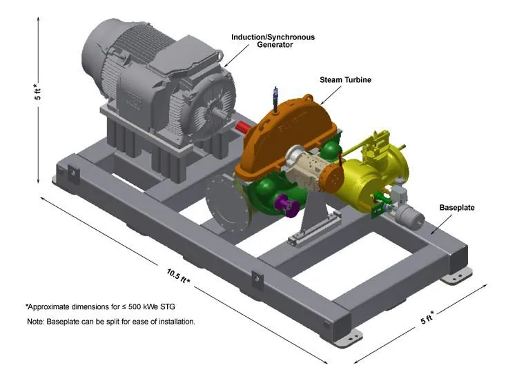
Steam turbine driven induction generators have a much smaller footprint when compared with diesel, gas or propane powered reciprocating engines and also with gas turbines. Steam turbines are relatively compact in design compared to the other prime mover options. The dimensions in the 500 kW unit shown above comprises just over 50 square feet of floor space and the entire unit including the base is only 5 feet high.
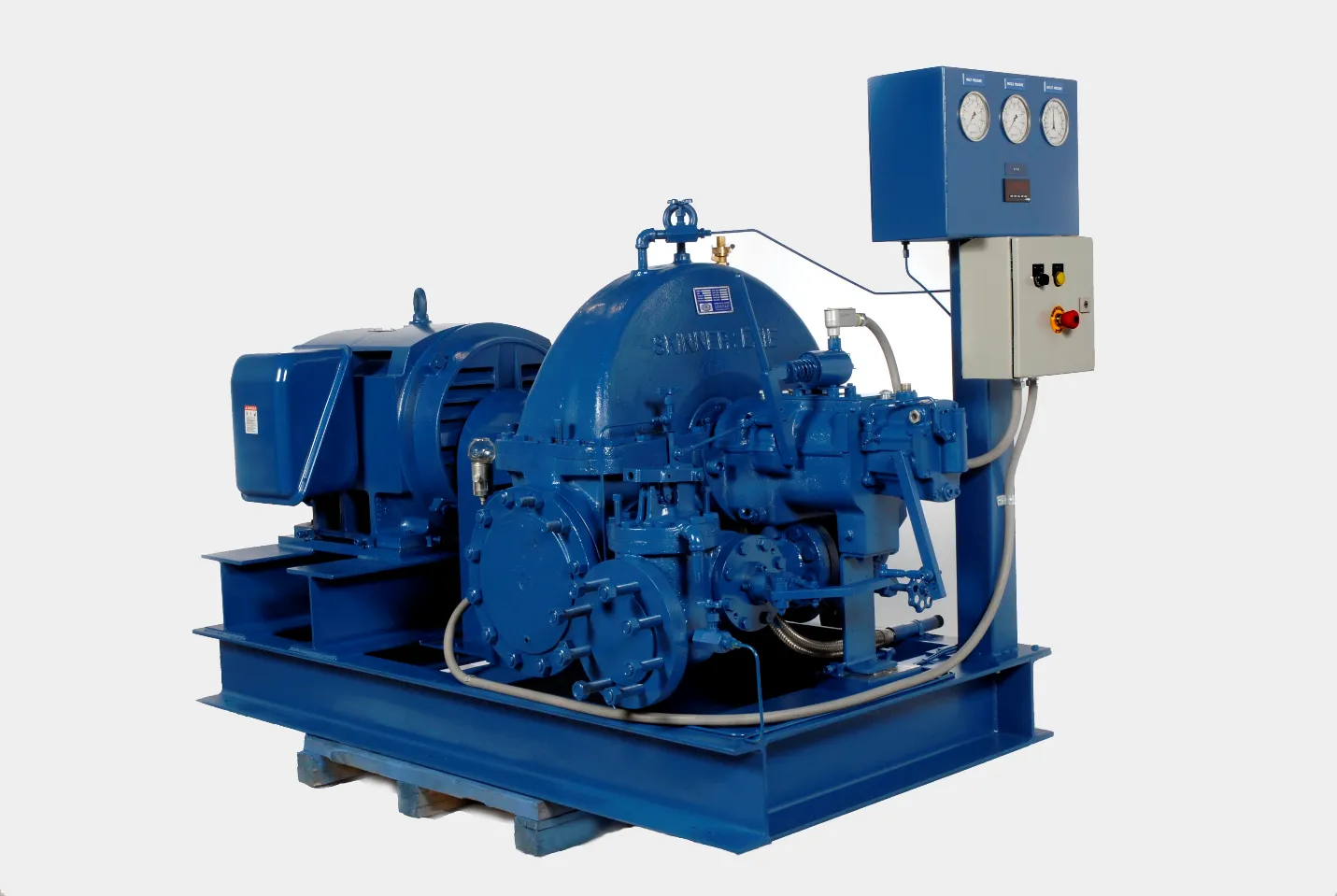
Below are some examples of steam turbine-driven induction generators provided by Skinner Power Systems of Erie, Pennsylvania.
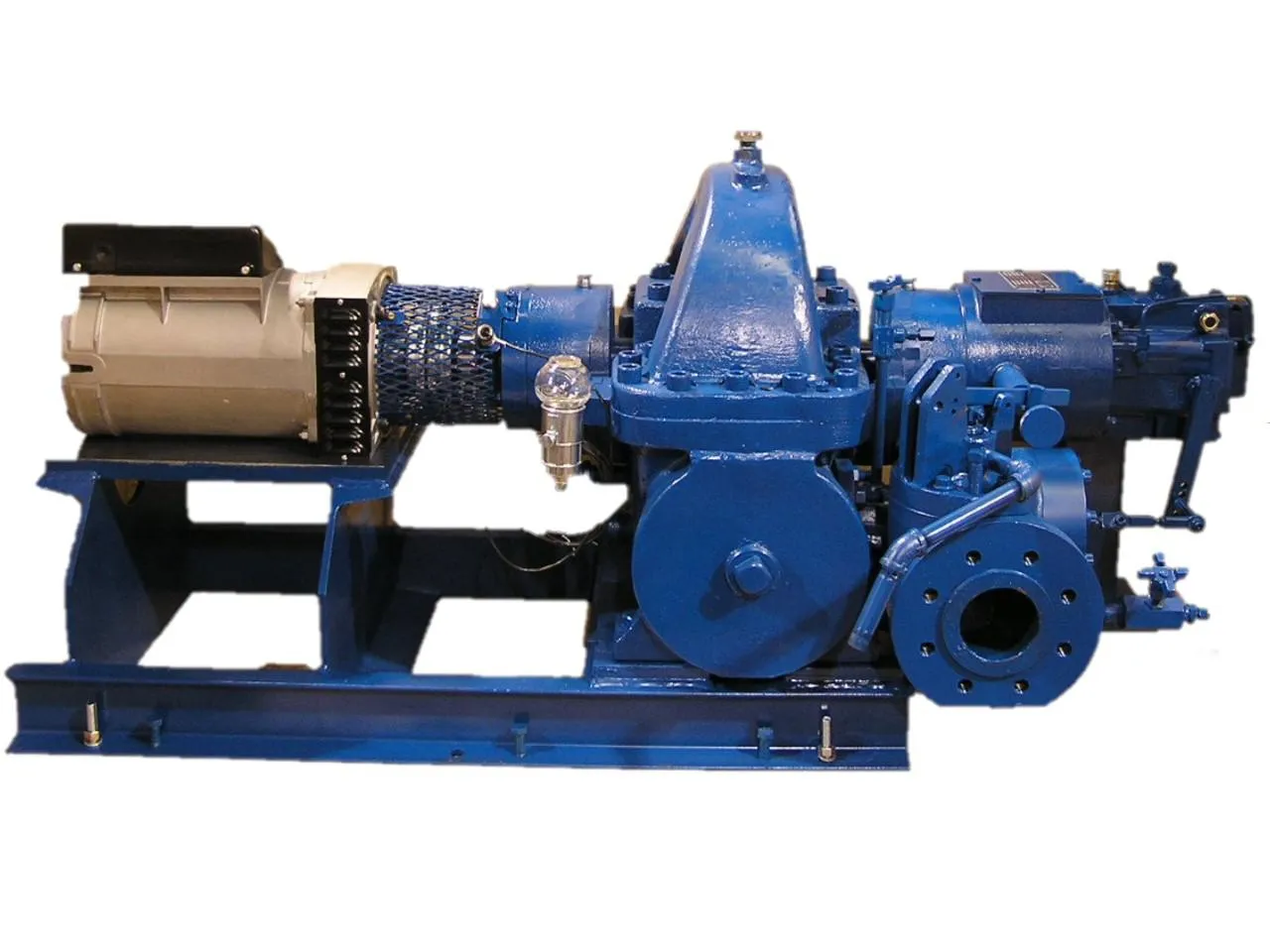
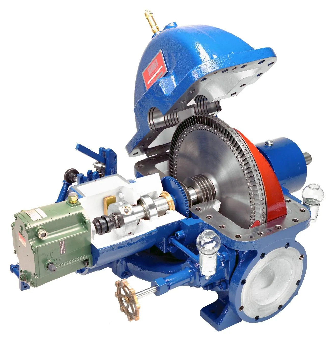
Below is a cutaway view of a Skinner steam turbine that would typically be coupled with an induction generator package.
Bullard Industrial Technologies, Inc.
E-mail: bullardindustrialtech@protonmail.com